A Better Antenna Calibration Improves the Measurement, Not Every Part of the Radio Link
Read NIST's new antenna-calibration announcement, convert dBi to power ratios and trace a link budget without confusing measurement uncertainty with coverage.
An antenna specification lists gain to several decimal places. A radio designer enters the number into a link budget and obtains a precise-looking received-power estimate. The extra digits are useful only if the gain measurement, reference conditions and rest of the budget justify them.
On 29 October 2026, NIST announced a broadband antenna-gain calibration service for dual-ridge horn antennas. NIST reports typical gain uncertainty of approximately ±0.07 dB across the stated 1–18 GHz range. The announcement concerns a measurement service and its conditions; it is not a guarantee that an installed antenna will provide the same advantage in every environment.
This guide connects that advance to three practical questions: what a gain number means, how it enters a radio-link calculation, and which uncertainties remain after a calibration improves.
Start with the reference behind the number
Gain describes how an antenna concentrates radiation in a direction relative to a reference, with relevant losses included according to the gain definition. The suffix in dBi identifies an isotropic reference: an ideal source radiating equally in every direction.
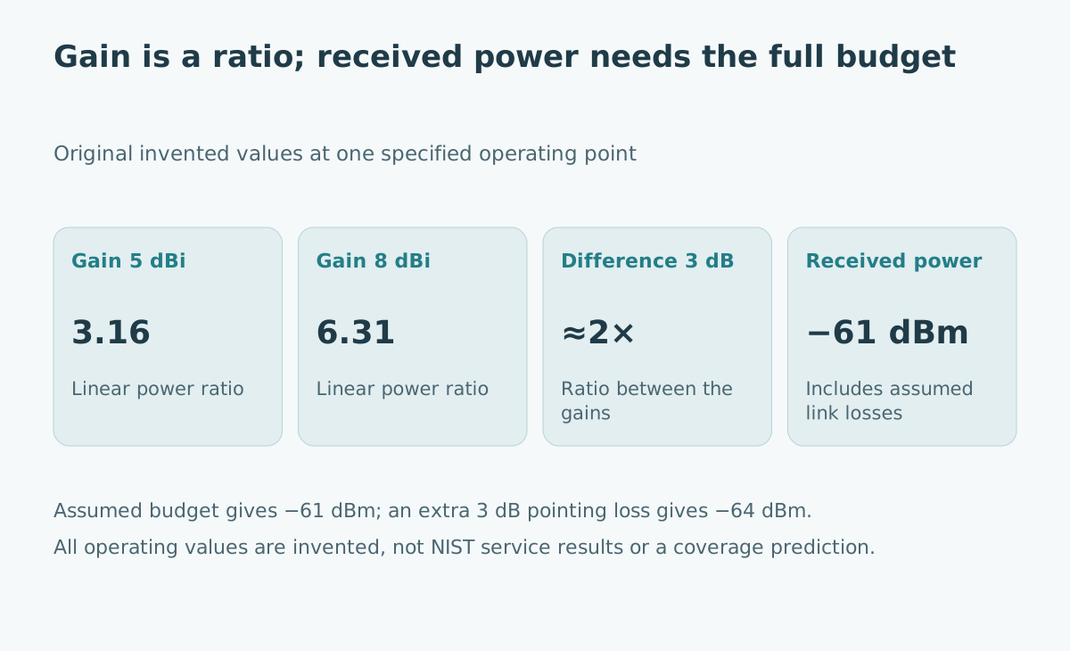
NASA's telecommunications primer explains this reference and the logarithmic conversion between gain in decibels and a power ratio. A gain of 5 dBi corresponds to 10^(5/10), approximately 3.16. A gain of 8 dBi corresponds to 10^(8/10), approximately 6.31.
Those numbers do not mean the passive antenna creates extra total transmitter power. They describe a directional comparison. Ask which frequency, polarization, direction and measurement reference apply before comparing two specifications.
Compare differences in decibels with ratios in linear units
The hypothetical gain difference between 8 dBi and 5 dBi is 3 dB. Its linear ratio is 10^(3/10), approximately 1.995, conventionally described as about twice the directional power ratio under otherwise comparable conditions.
| Original teaching quantity | Calculation | Approximate result |
|---|---|---|
| Gain 5 dBi | 10^(5/10) | 3.16 |
| Gain 8 dBi | 10^(8/10) | 6.31 |
| Difference 3 dB | 10^(3/10) | 2.00 |
Subtracting 8 minus 5 produces a decibel difference, not a linear gain of 3. Likewise, comparing the raw numbers 8 and 5 as a ratio of 1.6 would use the wrong scale.
Keep absolute power references separate too. A power expressed in dBm is referenced to one milliwatt. A directional antenna gain expressed in dBi is a ratio to an isotropic reference, not a power reading. The compatible logarithmic terms can be combined in a budget, but their labels should remain visible.
What the new calibration technique addresses
The NIST publication record for Gordon and Moser's July 2026 paper describes coordinated motion of two robotic antenna positioners. The antennas maintain their measurement relationship while moving relative to the chamber, allowing reflections from the chamber to be averaged out.
Its abstract reports demonstrations involving standard-gain and broadband dual-ridge horns. This addresses a specific measurement problem: chamber multipath can distort the inferred gain. The abstract and bibliographic record were reviewed for this article; the complete paper and uncertainty budget were not independently assessed.
The contribution is meaningful without extending it beyond that scope. It does not establish that reflections disappear from a customer's eventual operating site or that every antenna type can use the same service conditions.
Trace one complete hypothetical link budget
Assume transmitter output 20 dBm, a transmit-cable loss of 2 dB, transmit gain 5 dBi, modeled path loss 90 dB, receive gain 8 dBi and receive-cable loss 2 dB. All quantities refer to one specified frequency and compatible orientation in this deliberately simplified example.
The received-power calculation is 20−2+5−90+8−2 = −61 dBm. It is an assumed budget, not a measurement. The large negative number is compatible with a small positive power because dBm uses a logarithmic reference.
Now add an assumed 3 dB pointing loss. The predicted received power becomes−64 dBm. Improving knowledge of the antenna gain does not remove that pointing loss. A real budget also needs appropriate treatment of polarization, environment, receiver noise and the required signal quality.
Before claiming adequate margin, define the receiver criterion for the intended modulation, rate and error performance. Received power alone cannot establish successful data transfer for every configuration.
Read the uncertainty statement with its conditions
NIST Technical Note 1297 explains expanded uncertainty in terms of a coverage factor and the underlying uncertainty evaluation. A certificate should identify the measured quantity, conditions and uncertainty basis. Do not treat a quoted ± value as a universal maximum error or invent its confidence level.
For an original mathematical illustration, a stated 0.2 dB upward change corresponds to a power ratio of 10^(0.2/10), approximately 1.047. The same magnitude downward gives approximately 0.955. The interval is symmetric in decibels but multiplicative in linear units.
These are conversions of an assumed interval, not a claim about NIST's reported coverage. Nor should separate uncertainty terms automatically be added as if they were worst-case bounds or statistically independent standard uncertainties. Their meanings and correlations determine the appropriate combination.
Preserve the calibration chain through installation
The antenna may be calibrated at a defined connector plane and orientation. Your installed system may add a cable, adapter, radome or mounting arrangement. Record what changed rather than assuming the original result applies unchanged to the entire assembly.
An original acceptance worksheet can contain the antenna identifier, certificate, frequency range, reference plane, installed accessories and any subsequent checks. Keep the calibration result distinct from an on-site performance test.
For example, an installation can have an accurately known antenna gain but an incorrectly recorded cable loss. The budget can remain wrong. The useful review follows the whole chain of quantities, not only the specification with the smallest uncertainty.
Match the evidence to the deployment claim
If the claim concerns antenna calibration, inspect the certificate and method scope. If it concerns a working radio link, inspect the complete configuration and representative operating tests. If it concerns geographic coverage, the propagation model and environmental evidence also matter.
Treat a change in frequency, antenna orientation or physical installation as a reason to review the assumptions. A narrowly measured component property can support a larger engineering case, but it does not replace that case.
The related measurement-uncertainty and guard-band guide explains why the measured quantity, uncertainty and acceptance decision should remain separate. Here, the same discipline prevents an improvement in laboratory metrology from becoming an unsupported promise about every radio user's experience.
Sources and evidence limits
- NIST broadband antenna-gain calibration announcement, 29 October 2026; service scope, frequency range and stated typical uncertainty reviewed.
- Gordon and Moser, Improved Broadband Antenna Gain Measurements, 9 July 2026; primary paper abstract and publication record reviewed.
- NIST Technical Note 1297, Expanded Uncertainty, foundational uncertainty guidance checked 31 October 2026.
- NASA, Basics of Space Flight: Telecom, foundational gain-reference and decibel explanation; checked 31 October 2026.
All numerical gain conversions and link-budget inputs are original examples. No equipment recommendation, actual field coverage, complete uncertainty budget or independent validation of the calibration service is claimed.