A Smaller Optical Frequency Ruler Is a Step Toward a Portable Clock, Not the Whole Clock
Understand the new optical microcomb research, how frequency spacing and offset work, and what engineers must verify before calling a clock field-ready.
A ruler is useful because its marks are both regularly spaced and connected to a reference. A beautifully printed strip with unknown spacing cannot measure a board reliably. Measuring light has an analogous problem: scientists need an organized set of frequencies whose relationships they can determine and maintain.
On 16 October 2026, NIST described a new chip-based optical frequency comb, highlighting potential for mobile timekeeping. The research uses two lasers and a small resonator to generate an optical frequency ruler. NIST identifies it as an enabling component for future applications, including navigation when satellite signals are unavailable.
The useful engineering question is what the demonstrated component enables, and what must still be established for an entire device. A reduced-size frequency comb and a complete, qualified portable atomic clock are different claims.
Why regularly spaced colors form a useful ruler
Each color corresponds to an electromagnetic frequency. A comb produces many narrow frequency lines with an organized spacing, making it possible to connect optical measurements with lower-frequency signals that electronics can handle.
NIST's frequency-comb primer describes this as a gearing function between optical oscillations and microwave-frequency signals. The comb helps transfer or compare frequency information; it does not automatically supply an accurate atomic reference simply by producing many colors.
For a measurement system, ask what establishes its reference, how the comb is controlled and what signal is finally delivered to the user. A component can preserve a relationship accurately while the external reference itself has drifted.
What changed in the new research
The Nature paper by Moille and colleagues, published 30 September 2026, describes a self-aligned microcomb formed between two octave-separated pump lasers. An octave means a factor of two in frequency, not a fixed difference measured in hertz.
The paper's abstract reports three demonstrations: optical frequency synthesis, low-noise millimeter-wave generation and integrated optical-clock readout. That is evidence of several metrology functions using the platform. It is not, by itself, a specification for a finished consumer navigation product.
The research team's JQI account explains why strong, usable edge frequencies and alignment matter: a comb with overlapping sets of marks is a poor ruler. The architecture addresses a specific obstacle in making an optical measurement tool more practical.
Separate spacing, offset and tooth identity
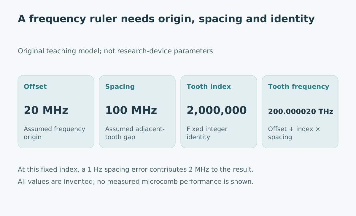
A simplified standard description writes a comb tooth's frequency as f(n) = f(offset) + n × f(spacing). The integer n identifies the tooth. Knowing only the spacing leaves the absolute starting position unknown; knowing the offset without the tooth number is also insufficient.
Think of a numbered building directory. Equal floor heights help locate a room only if the ground reference and floor identity are known. For light, the quantities are frequencies rather than heights, but the bookkeeping principle is similar.
A readout can therefore need more than a clean-looking spectrum. The measurement process must establish the relevant frequency relationship and the identity of the signal being used. The exact implementation varies; the equation here is a teaching model rather than a full description of the new experiment.
Calculate one entirely hypothetical tooth
Assume an invented offset of 20 MHz, tooth spacing of 100 MHz and tooth index 2,000,000. The calculation is 20 MHz + 2,000,000 × 100 MHz = 200,000,020 MHz, or 200.000020 THz.
| Teaching-model input | Assumed value | Role in the calculation |
|---|---|---|
| Offset | 20 MHz | Sets the frequency origin |
| Tooth spacing | 100 MHz | Sets the gap between adjacent teeth |
| Tooth index | 2,000,000 | Identifies the selected frequency line |
| Calculated tooth frequency | 200.000020 THz | Result under the three assumptions |
None of these values is taken from the new device. The original example is deliberately simple enough to audit with unit conversion. One terahertz is one million megahertz; a misplaced conversion would overwhelm the extra digits that make the result look precise.
Precision in a display does not establish measurement accuracy
Keep the assumed tooth index fixed. If the spacing used in the calculation is wrong by 1 Hz, its contribution at tooth 2,000,000 is 2,000,000 Hz, or 2 MHz. This is sensitivity arithmetic: n × spacing error. It is not a measured microcomb error or a realistic uncertainty budget for the reported device.
The lesson is that a small error in a repeated interval can matter after multiplication. Conversely, more printed digits do not prove that the underlying interval is known sufficiently well. A real uncertainty evaluation also needs reference uncertainty, measurement correlations, control behavior and other relevant effects.
For a related engineering distinction, see measurement uncertainty and manufacturing guard bands. In both cases, the claimed result needs a measurement chain, not merely a finely resolved display.
Review the rest of the clock as a system
A fictional procurement review should separate the atomic reference, light source, comb, control electronics, power supply, thermal management and usable output. Miniaturizing one item may remove an important obstacle while leaving other components responsible for the final package size or energy demand.
Ask vendors for the boundary of every specification. Does “chip-scale” describe the resonator, the optical assembly or the complete instrument? Does the reported power include lasers, temperature control and readout electronics? Was the measurement taken after a long stabilization period?
These are original review questions, not allegations about missing work in the paper. Their purpose is to prevent a genuine component advance from being stretched into an unsupported statement about an entire product.
Match the demonstration to the intended application
For a hypothetical mobile instrument, define the required output signal, acceptable interruption, operating environment and start-up behavior. Then request evidence for that specific configuration. An optical measurement performed on a controlled bench does not automatically characterize performance during movement, temperature changes or power interruptions.
A sensible staged review could first reproduce the intended measurement, then test recovery after a controlled interruption, and finally evaluate the packaged configuration under its specified environmental conditions. Record changed hardware and control settings between stages.
Navigation is especially easy to overstate. A stable time or frequency reference can support navigation, but position estimation also depends on the rest of the sensing and signal architecture. Do not convert the phrase “could support GPS-independent navigation” into “this chip alone replaces GPS.”
Sources and evidence limits
- NIST, Chip-based tape measure for light, 16 October 2026, updated 27 October 2026; official research announcement.
- Moille and colleagues, Nature paper, published 30 September 2026; abstract and bibliographic record reviewed, not the complete paper or supplementary data.
- JQI, Frequency-comb research account, October 2026; researchers' institutional explanation.
- NIST, Optical frequency combs, foundational explanation; checked 30 October 2026.
The numerical example and procurement worksheet are original. No measured performance, commercial availability, environmental qualification or finished-clock specification is inferred from the illustrative values.